
In this post, you’re going to learn about error detection in computer networks with the help of proper examples and diagrams.
Let’s get started, happy learning!
Errors in Networking
In computer networks, devices are connected to each other and share information through a network. The data sent by the sender might be corrupted or lost during the transmission of data, as data is sent in the form of signals.
The interfaces can change the shape of a signal and such changes can alter the meaning of data.
An error is a situation when data received at the destination machine is not the same as data that is actually sent by the source machine.
Types of Errors
Basically, there are two types of errors that can occur during the transmission of data. The types of errors are as follows.
Single Bit Error: The term single bit error means that only one bit of a data unit is changed from 1 to 0 or from 0 to 1.
Burst Error: The term burst error means the two or more two bits of the data unit is changed from 1 to 0 or vice versa.
Error Control in Computer Networks
The data link layer uses error control techniques to ensure that the destination machine should receive the exact data or message. But sometimes the data gets corrupted or lost during the transmission.
The data link layer uses the two error control techniques. These techniques are used to identify the error and to correct that error. The following are the error correction techniques,
- Error Detection
- Error Correction
Error Detection in Computer Networks
Error detection in computer networks is the process of detecting or identifying an error in the data or message. The data link layer uses various error detection techniques for this purpose.
The basic approach is the use of redundancy, where additional bits are added to facilitate the detection and correction of errors.
Error Detection Techniques:
Following are the different types of error detection techniques that we use for detecting an error in computer networks,
- Simple parity check
- Two-dimensional parity check
- Checksum
- Cyclic redundancy check.
Simple Parity Check
Simply parity check is the most simple mechanism of error detection in computer networks and a parity bit is used in this technique. Parity is simply an additional bit and is also called a redundant bit. A parity bit is appended at the end of the data unit before transmitting the data.
This will increase the size of the data because we are adding one extra bit with the data. For example,–If we are sending the 8-bit data, then after appending the parity bit, the size of the data block will become 9 bits.
There are two types of parity bits that can be added for error detection as follows:
Even Parity: In even parity, an additional bit is added at the end of the data block to make the no. of 1’s even.
If the no. of 1’s is already even in the data, then the parity bit 0 is added. If the no. of 1’s is odd in the data block, then the parity bit 1 is added.
Odd Parity: In odd parity, an additional bit is added to make the no. of 1’s odd.
If the no. of 1’s is already odd in the data unit then, parity bit 0 is added at the end of the data unit. If the no. of 1’s is even then parity bit 1 is added.
Working of Simple Parity Check
Simple parity check uses the two circuits parity generator and parity checker. The parity generator is used at the sender end’s side and it adds parity bit with the data. The parity bits are transmitted along with the data unit.
At the receiving end, another circuit is used, which is a parity checker. It checks the parity bits. If the sent parity bits are equal to the received parity bits, then there is no error and receiving machine accepts the data.
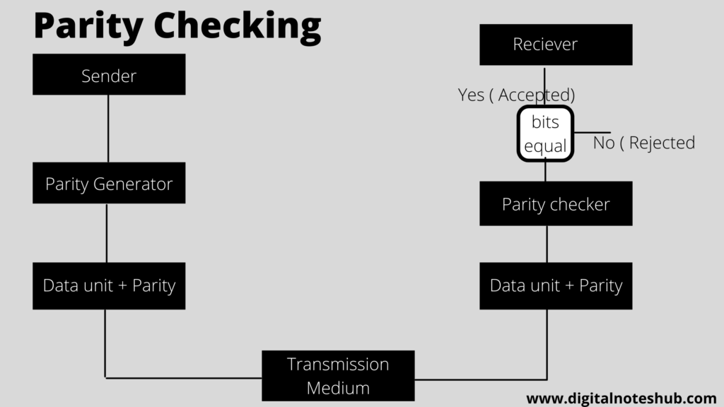
If the sent parity bits are not equal to the received, then it shows an error in the data and the data gets rejected. The above diagrams show the basic function of parity checking error detection.
There is one major drawback of a simple parity check that it can only detect a single-bit error. If the data has multiple errors, then it cannot detect the errors.
Two Dimensional Parity Check
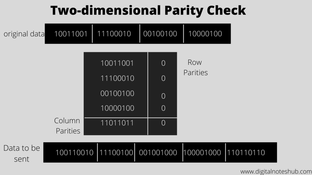
A table is used to arrange the data in a two-dimensional parity check. In this technique, the whole data is divided into rows. Row and column parities are calculated. Parity bits are appended at the end of the data block and these parity bits are sent along with data.
Take the example of the following data to understand the concept of a two-dimensional parity check.
Checksum
A checksum in computer networks is another error detection technique. The concept of redundancy is used in this technique to identify errors. The major two components of the checksum are the checksum generator and checksum checker.
A checksum generator is used on the sender’s side and it divides the whole data into k segments and each segment has n bits. All the segments are added using 1’s complement, and the sum is calculated.
Then the sum is complemented to generate the checksum. The data segments are then transmitted along with the checksum field from the sender to the receiving machine.
At the receiving end, another circuit is used, which is called a checksum checker. The primary function of the checksum checker is to check the checksum and verify the errors in the receiving data.
It divides the data into k sections and each section has n bits. All the segments are added to each other and the complement of the sum is calculated. The working of checksum is shown in the above figure.
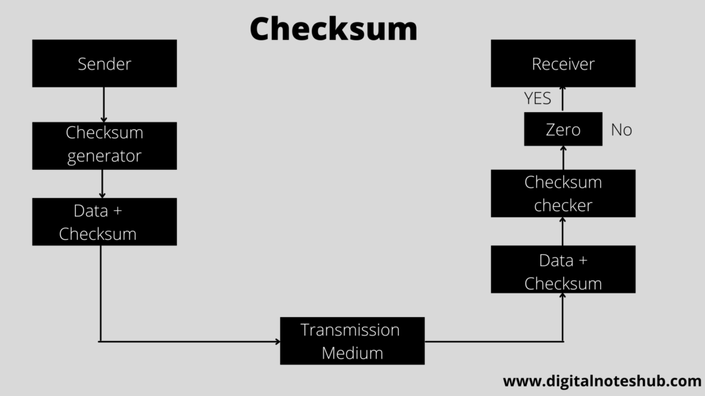
If the result is zero, then there is no error and the receiver will receive the data.
If the result is non zero, then it shows the data has some error and data gets rejected at the receiving end.
There are mainly five types of checksum in computer networks for error detection
- Integer addition checksum
- One’s complement checksum
- Fletcher checksum
- ATN checksum
- Adler checksum
Cyclic Redundancy Check (CRC)
Cyclic redundancy check (CRC) in computer networks is another important error detection technique. The binary division is used in this mechanism. The redundant bits that are added at the end of the data are called cyclic redundancy check bits.
This technique uses two circuits, which are the CRC generator and the CRC checker. CRC generator is used at the sender’s side to generate CRC bits and a CRC checker is used to verify the bits at the receiver end.
Working of CRC in Computer Networks
In the CRC technique, the following steps are performed.
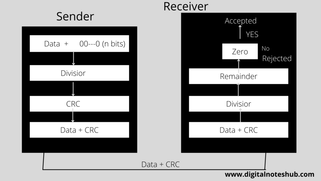
- N no. 0’s are added at the of the data unit. The no. of zeros should be one less than the no. of bits of a predetermined number (Divisor).
- The binary division operation is performed on the extended data.
- After performing binary division, the remainder is calculated, and this is called CRC remainder.
- The CRC remainder is appended at the end of the actual data unit. The actual data unit, along with the CRC remainder, is transmitted.
- The receiver receives the actual data + CRC remainder and the binary division is performed on this using the same divisor.
- CRC checker verifies the CRC bits.
- If the result of the division is zero, then it shows that data has no error, and the receiver accepts the data.
If after performing the division, the result is non zero, then it shows the error and data gets rejected at the receiver end.
Your Feedback
Have you enjoyed this tutorial on error detection in computer networks? Post your thoughts in the comment box below.